Pin Configuration:
WTC6104BSI pin configuration diagram is shown below:

Figure 1: WTC6104BSI Pin Diagram
Definitions of Pins
Pin No. | Pin Name | Usage | Function Description |
1 | SLOCK_S | | | Selection of output mode Connecting VCC will enable ordinary soft-touch key mode Connecting GND will enable self-locking key output mode |
2 | HLS | | | Selection of initial level of output pin Connect VCC, and the initial level of output pin is high. Connect GND, and the initial level of output pin is low. |
3 | SW3 | | | Interface of touch key 3 (sensor pad 3) |
4 | SW2 | | | Interface of touch key 2 (sensor pad 2) |
5 | SW1 | | | Interface of touch key 1 (sensor pad 1) |
6 | SW0 | | | Interface of touch key 0 (sensor pad 0) |
7
| CSEL | | | Capacitor interface for adjusting the sensitivity |
8 | GND | | | Power ground |
9 | OUT0 | O | SW0 status output |
10 | OUT1 | O
| SW1 status output |
11 | /RES | | | IC reset pin |
12 | VCC | | | Power input |
13 | OUT2 | O | SW2 status output |
14 | OUT3 | O | SW3 status output |
15 | BUZZ | O | Buzzer control pin |
16 | BLC | O | Backlight LED control pin |
Multi-key (SHIFT) Working Mode:
Figure 4 is operating circuit diagram of WTC6104BSI in 4-key non-self-locking mode:
The channel matched resistance R0-03 should be placed into IC as much as possible.

Figure 4: WTC6104BSI Application Schematic Diagram
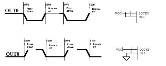
Output in Non-self-locking Mode:
When LOCK_S is connected to VCC, WTC6104BSI will adopt the output mode of ordinary soft-touch switch.
When the occurrence of effective touch on sensor pad is detected, the corresponding indicative pin will
output reversal, and when the finger leaves, the indicative pin will be recovered to output the initial level.
Take SW0 channel as an example, the relationship between output signal and sensor input channel is as
shown in Figure 3, and other channels are the same.

Figure 2: Output Sequence Diagram of Keys when WTC6104BSI is in Non-self-locking Mode
Output in Self-locking Mode
When LOCK_S is connected to GND, WTC6104BSI will adopt the output mode of self-locking switch. When the occurrence of effective touch on sensor pad is detected, the corresponding indicative pin of sensor pad will output reversal of level, and when the finger leaves, the output level of indicative pin will remain the same. Take SW0 channel as an example, the relationship between output signal and sensor input channel is as shown in Figure 4. Other channels are the same.

Figure 3: Output Sequence Diagram of Keys when WTC6104BSI is in Self-locking Mode