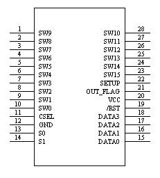
Definitions of WTC6216BSI Pins:
WTC6104BSI Pin Diagram

Figure 1: WTC6104BSI Pin Diagram
Definitions of WTC6216BSI pins
Pin No. | Pin Name | Usage | Function Description |
1 | SW9 | | | Interface of touch key 9 (sense element 9) |
2 | SW8 | | | Interface of touch key 9 (sense element 8) |
3 | SW7 | | | Interface of touch key 9 (sense element 7) |
4 | SW6 | | | Interface of touch key 9 (sense element 6) |
5 | SW5 | | | Interface of touch key 9 (sense element 5) |
6 | SW4 | | | Interface of touch key 9 (sense element 4) |
7 | SW3 | | | Interface of touch key 9 (sense element 3) |
8 | SW2 | | | Interface of touch key 9 (sense element 2) |
9
| SW1 | | | Interface of touch key 9 (sense element 1) |
10 | SW0 | | | Interface of touch key 9 (sense element 0) |
11 | CSEL | O | Capacitor interface for adjusting the sensitivity |
12 | GND | | | Power ground |
13 | S0 | | | The S0 must be connected to VCC usufully for the internal test foot |
14 | S1 | | | The S1 must be connected to VCC usufully for the internal test foot |
15 | DATA0 | |/O | BCD code output and sensitivity fine adjustment input
|
16 | DATA1 | |/O | BCD code output and sensitivity fine adjustment input
|
17
| DATA2 | |/O | BCD code output and sensitivity fine adjustment input
|
18 | DATA3 | |/O | BCD code output and sensitivity fine adjustment input |
19 | /RST | | | Chip reset pin |
20 | VCC | | | positive power supply output |
21 | OUT_FLAG | O |
Key state indicator: 1 indicates that the key has no effective touch; 0 indicates that there is a key pressed
|
22 | SETUP | | |
The symbol of sensitivity fine adjustment input: setting 0 indicates that the sensitivity is input and set by the user; when setting 1, it indicates that IC normally performs the test work.
|
23 | SW15 | | | Interface of touch key 15 (sense element 15) |
24 | SW14 | | | Interface of touch key 15 (sense element 14) |
25 | SW13 | | | Interface of touch key 15 (sense element 13) |
26 | SW12 | | | Interface of touch key 15 (sense element 12) |
27 | SW11 | | | Interface of touch key 15 (sense element 11) |
28 | SW10 | | | Interface of touch key 15 (sense element 10) |
Output Display:
Sequence diagram of BCD interface output
When the effective touch occurred on the induction disk is detected, the WTC6216BSI outputs the BCD code of the corresponding induction disk in 200ms, so that the user MCU can process it. The OUT_FLAG foot indicates the state of the key; 1 indicates that the key has no effective touch, and 0 indicates that it has a key pressed. The sequential relationship between the OUT_FLAG and BCD code output feet (DATA3 ~ DATA0) is shown in Figure 2

Figure 2: Sequence diagram of key output
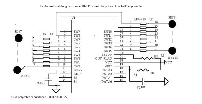
Peripheral Circuit:

Figure 3: WTC6216BSI Application Schematic Diagram