Definitions of WTC68K1R Pins:

Figure 1
Definitions of WTC62K1R Pins:
| Pin No. | Pin Name | Usage | Function Description |
| 1 | SW8 | | | Touch key (induction disc) interface 6 |
| 2 | SW9 | | | Touch key (induction disc) interface 7 |
| 3 | SW10 | | | Roller induction disc unit interface |
| 4 | SW11 | | | Roller induction disc unit interface |
| 5 | SW12 | | | Roller induction disc unit interface |
| 6 | SW13 | | | Roller induction disc unit interface |
| 7 | SW14 | | | Roller induction disc unit interface |
| 8 | SW15 | | | Roller induction disc unit interface |
9
| CSEL | | | Roller induction disc unit interface |
| 10 | GND | | | Roller induction disc unit interface |
| 11 | CODER1 | O | Sensitivity adjustable capacitor interface |
| 12 | CODER0 | O | Power ground |
| 13 | OUT A | O | Roller encoder pulse output A |
| 14 | OUT B | O | Roller encoder pulse output B |
| 15 | OUT2 | O | The output of BCD code and the input of the fine tuning, and the output of the roller encoder pulse is 0 |
| 16 | OUT3 | |/O | The output of BCD code and the input of the fine tuning, and the output of the roller encoder pulse is 1 |
17
| /RST | | | The output of BCD code and the input of the fine tuning, and the output of the roller encoder pulse is 2 |
| 18 | VCC | | | Touch key SW3 status output |
| 19 | BLC | O | Chip reset pin |
| 20 | BUZZ | O | positive power supply output |
| 21 | SW0 | | | The Key state indicator: 1 indicates that there is no key pressed in the key; 0 indicates that there is key pressed |
| 22 | SW1 | | | The input signal of the sensitivity adjustment: setting 0 indicates that the user input the set sensitivity; when setting 1, it indicates that the module performs the test work normally |
| 23 | SW2 | | | Touch key (induction disc) interface 0 |
| 24 | SW3 | | | Touch key (induction disc) interface 1 |
| 25 | SW2 | | | Touch key (induction disc) interface 2 |
| 26 | SW2 | | | Touch key (induction disc) interface 3 |
| 27 | SW3 | | | Touch key (induction disc) interface 4 |
| 28 | SW3 | | | Touch key (induction disc) interface 5 |
Peripheral Circuit:
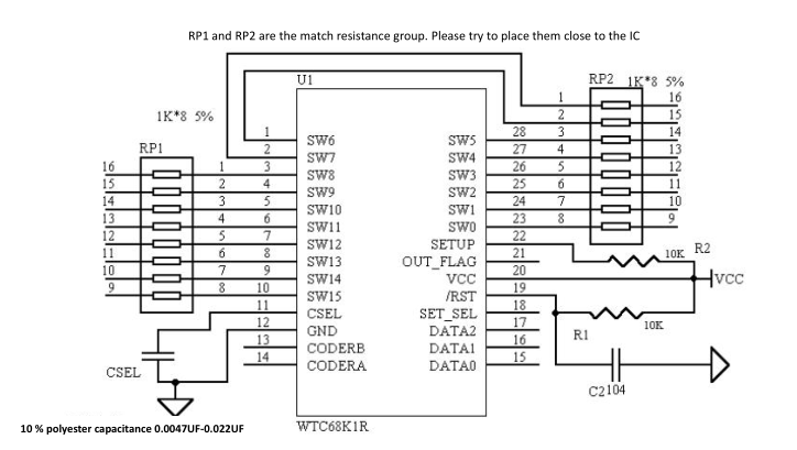
The peripheral circuit of WTC68K1R is very simple, and only needs a few resistors and capacitors. The key component is capacitor CSEL for adjusting the sensitivity and IK resistance group for measuring the matched impedance of circuit. CSEL should use 10%-precision polyester capacitor, capacitor made of NOP material or capacitor made of X7R material . 1K resistance group can provide you with the best and most stable measurement effect, and CSEL and matched resistance shall be placed as close as possible to IC at PCB layout.
Figure 4 below shows the peripheral circuit diagram of WTC68K1R application
 Figure 4: WTC68K1R Application Schematic Diagram
Output Display:
The output of the touch key:
After the effective touch occurred is detected, WTC68K1R in 200ms will set the OUT FLAG leg in low indicator state.At this time, the external MCU of the customer can read the key value of the touch through the module BCD code data port. After the user's finger leaves the touch key, the OUT FLAG leg is automatically setting high.

Figure 2: Sequence diagram of the output of the key
Touch rotary encoder output:
The operation mode and output signal of the touch roller are consistent with the common mechanical roller encoder. But there is no the burr of mechanical output pulse. The user does not have to handle the soft and hardware aiming at the burr

Figure 3: Sequence diagram of touch roller output
The rotation of roller gives 30 pulses a week.
The phase difference between the two pulses is around 6ms