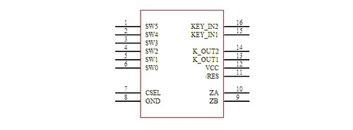
Definitions of WTC62K1R Pins:

Figure 1
Definitions of WTC62K1R Pins:
| Pin No. | Pin Name | Usage | Function Description |
| 1 | SW5 | | | Roller induction disc unit interface |
| 2 | SW4 | | | Roller induction disc unit interface |
| 3 | SW3 | | | Roller induction disc unit interface |
| 4 | SW2 | | | Roller induction disc unit interface |
| 5 | SW1 | | | Roller induction disc unit interface |
| 6 | SW0 | | | Roller induction disc unit interface |
| 7 | CSEL | | | Sensitivity adjustable capacitor interface |
| 8 | GND | | | Power ground |
9
| ZB | O | Roller encoder pulse output B |
| 10 | ZA | O | Roller encoder pulse outputA |
| 11 | /RST | | | Chip reset pin |
| 12 | VCC | | | positive power supply output |
| 13 | K_OUT1 | O | Touch key 1 output |
| 14 | K_OUT2 | O | Touch key 2 output |
| 15 | KEY_IN1 | | | Touch key 1 (induction disc) input interface |
| 16 | KEY_IN2 | | | Touch key 2 (induction disc) input interface |
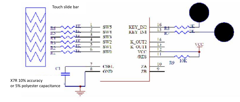
Peripheral Circuit:
RP1 and RP2 are the match resistance group. Please try to place them close to the IC

Figure 4: WTC62K1R Application Schematic Diagram
The output of the touch key:
When the occurrence of effective touch on the sense element is detected, WTC62K1R will output the status of corresponding sense element channel within 100ms, so that it can be processed by user MCU, or directly drive the execution circuit to work The relationship between the output signal and the touch key input channel is shown below The signal output does not have the output jitter of the mechanical key. The user does not need to make mechanical key to jitter.

Figure 2: Sequence diagram of the output of the key
Touch rotary encoder output

Figure 3: Sequence diagram of touch roller output
The rotation of roller a week gives 20 pulses. One pulse is divided into four beats such as 01,10,11. and 10,00,01,11。
The phase difference between the two pulses is around 2.5ms.